Unintentional radio frequency interference (RFI) to GNSS signals has many causes, but it is mostly tied to the growth of the communications sector. Two of the most common sources of significant GNSS interference for aircraft are Iridium antennas and active fleet tracking antennas. Applanix has developed ways to mitigate both.
Overcoming Iridium and Fleet Tracking Antennas with Iridium Filters, Inertial Navigation
Antennas for the Iridium, satellite-based voice and data communications system are most common at military bases and airports, and have a frequency that is very similar to that of GNSS observations. There are many of them, and they cause significant degradation to GNSS observations in their vicinity. To overcome this challenge, Applanix has built an Iridium filter into the primary antenna that it sells for airborne platforms, which clamps down on some of the higher frequency ranges of GNSS observations. (These filters are only for manned airborne platforms, because they are too large and heavy to fit on UAVs.)
Active fleet tracking systems typically require two GNSS antennas, both installed on the body of an aircraft: one is passive, observing GNSS signals, and one is active, broadcasting those observations to a fleet management software. If they are too close to each other, the active frequency will interfere extremely with the observations. The first preventative measure against this interference is to separate the two antennas by at least 2 meters. (In fact, Applanix routinely recommends that, wherever possible, one should move the GNSS antenna at least a meter from any external technology that might cause disturbance.) Unfortunately, even with significant separation the signal can still be degraded. The ideal, with regards to GNSS accuracy, would be to not use active antennas on aircraft at all. Another frequent cause of cycle slips and dropped observables in aircraft are high bank angles.
Inertial navigation helps to mitigate these effects, regardless of their cause. When a receiver loses track of fixed integer ambiguity on GNSS observations, the error bounds grow astronomically in all directions because the receiver has minimal information on where to search once it reacquires a fix. An inertial navigation system (INS), however, can greatly constrain the search area by calculating the aircraft’s speed and heading. This technique, called inertially-aided kinematic ambiguity resolution (IAKAR), is implemented on all Applanix receivers. A further advantage of this approach is that it removes some of the collection constraints that previously used to create difficulty and inefficiency, such as having to fly flat to avoid cycle slips.
The Advantage of IAKAR and Post-Processing
On land, multipath from buildings and obstructions greatly reduce GNSS accuracy; urban canyons and dense vegetation canopies reduce it further, while tunnels cause complete outages. In all these scenarios, IAKAR and custom antennas, coupled with forward and reverse processing methods, substantially temper the problem in two ways: by reducing the carrier phase ambiguity search radius during signal reacquisition, and by actively rejecting bad observations, thereby greatly reducing the errors in the final solution.
Post-Processing, Explained
Because INS navigates by dead-reckoning, errors compound over time. Therefore, the longer the GNSS outage, the greater the error. However, once GNSS observations return, the error quickly reverts to a small value, as shown in the graph below:

This characteristic curve makes it possible to use the raw observations in post-processing to reduce error during the outage by processing them both forward and in reverse in time, as seen below:
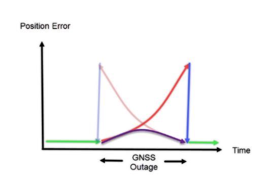
During the outage, both in the forward processed (dark red) and the backward processed (light red), the error peaks are quite large. Post-processing the raw data both forward and in reverse in time, then combining these solutions makes it possible to lessen the outage error and obtain greater accuracy represented by the purple line.